Initial view on VoWiFi in the 5G network
Introduction
In this post I provide a short overview of how the VoWiFi (Voice over WiFi) architecture may change in future 5G deployments. I haven’t participated in the 3GPP standardization groups, so this text is based on official 3GPP specifications and drafts only. I hope it will be valuable for engineers, who are currently working on EPC-based VoWiFi deployments and want to prepare for upcoming evolutions in the area of VoWiFi.
VoWiFi (or simply WiFi Calling) has gained a momentum as a novel Telco service for end users as they can now make phone calls via their own home WiFi Access Point. This service is especially important for users being abroad as they can use WiFi Calling instead of making expensive roaming calls. Along with VoLTE, the IMS-based voice services may replace the old 2G/3G technology.
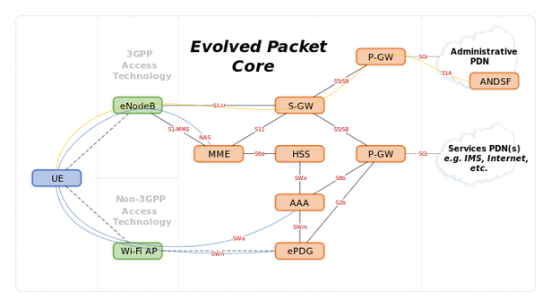
An implementation of VoWiFi has become possible with the emergence of the IP Multimedia Subsystem (IMS) and extensions to 3GPP LTE EPC architecture – evolved Packet Gateway (ePDG) and the AAA server. ePDG provides a secure gateway to service provider’s networks for users connected to untrusted WiFi access points. It leverages IPSec with the EAP-AKA authentication method on SWu interface as the security protocol. The AAA server provides security services for non-3GPP access. The ePDG is integrated with the rest of LTE. It is connected to P-GW over S2b interface using GTP tunneling, while the AAA server is integrated with HSS over SWx and to PGW over S6b interface. P-GW provides access for VoWiFi users to the IMS subsystem.

Although the 3GPP 5GSystem (5GS) specification is still in progress (the “Second Wave” of 5G specs has been delayed), a functional architecture of 5G RAN and Core has been already defined and should not be changed significantly (here you can find an introduction to the 5G system architecture). It’s already agreed that the VoWiFi architecture will need some changes to fulfill the requirements of 5G network. One of design pricinples that has been defined for 5G networks (TS 23.501), directly impacts the VoWiFi architecture:
“Minimize dependencies between the Access Network (AN) and the Core Network (CN). The architecture is defined with a converged core network with a common AN – CN interface which integrates different Access Types e.g. 3GPP access and non-3GPP access“
As 5G System is expected to be access-agnostic the interface between RAN and Core should be common for access technologies. Moreover, UEs should be allowed to communicate with core network over the NAS (Non-Access Stratum) interface, regardless current point of attachment. The NAS interface is a well-known in 3GPP systems, but in the current EPC-based VoWiFi architecture UE does not perform any signalling over the NAS interface. The principle of converged core network with a common AN-CN interface causes the change in architectural design.

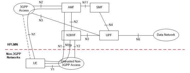
The 5G Core Network functions involved in the VoWiFi service are AMF, SMF, AUSF (control plane) and UPF (user plane). The Mobility Management Functions (MME) from 4G, which implements mobility, access and session management has been decomposed into AMF and SMF. AMF, which stands for Access and Mobility Function realizes access and mobility management functions, while SMF (Session Management Function) manages session connectivity. The decomposition is needed due to the emergence of new services (such as Internet of Things) requiring a differentiated session management. For instance, static IoT likely will not require session management and packets can be forwarded in the Best-Effort manner. Moreover, a control and user plane has been decoupled. Control plane functions has been moved from S-/P-GW to AMF and SMF. User plane functions (such as packet routing, forwarding, and encapsulation) are realized by UPF (User Plane Function).
In the 5G System specification the successor of eDPG is called N3IWF (non-3GPP InterWorking Function). The functionality of N3IWF at high-level is almost the same as ePDG – it provides a secure gateway to operator’s network for non-3GPP access technology. The interface between UE and N3IWF remains similar and is based on IPSec/IKE to establish a secure tunnel. As UE is expected to communicate with AMF over the NAS interface, there is a new N2 interface connecting N3IWF with AMF. Note that the N2 interface is considered to realized by a NG Application Protocol (NGAP) defined in TS 38.413. N3IWF is responsible for setting up the IPSec connection to be used by control plane traffic directed to AMF. As a consequence UE and N3IWF need to establish two IPSec Security Associations (SAs):
- Signalling (control plane) IPSec SA – it transports NAS messages destined to AMF,
- User plane IPSec SA – it transports packets destined to IMS
Signalling (control plane) IPSec SA
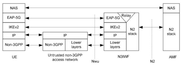
In the first step, UE and N3IWF must establish a signalling IPSec SA, which is used to securely exchange NAS messages between UE and AMF. The NAS interface is further leveraged to register UE in the 5G system. The below figure presents a control plane protocol’s stack used to establish signalling IPSec SA. Similarly to ePDG, IKEv2 protocol is used to setup security associations. However, the new authentication method – EAP-5G (or 5G AKA) – is introduced. The EAP method is used to encapsulate NAS messages between UE and N3IWF. Note that specification says that EAP-5G is “vendor-specific“.

When the signalling IPSec SA is established, the IPSec tunnel is configured to encapsulate NAS messages between UE and N3IWF. At this stage, UE can communicate with AMF to perform NAS signalling. It is presented in the figure below.

User plane IPSec SA
When UE is registered in the 5G system (via NAS interface) it can establish a new child IPSec SA (called user plane IPSec SA) to communicate with the IMS system. The procedure for establishing user plane IPSec SA is also supported by AMF.

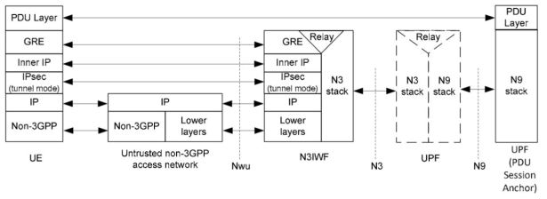
If IKEv2 procedure is finished, UE can communicate with P-CSCF (IMS gateway). A user plane protocol’s stack is depicted in the figure below. There are two main differences in comparison to the ePDG-based architecture:
-
The GRE (Generic Routing Encapsulation) protocol has been introduced to carry user data packets between UE and N3IWF. GRE allows to implement a flow-based QoS model as specified in TS 23.501. The GRE header carries QFI (QoS Flow Identifier) associated with user data packets. Optionally, N3IWF can indicate Reflective QoS Identifier (RQI). More on QoS in 5G networks here.
-
The new N3 interface between N3IWF and UPF. This interface is considered to be implemented based on GTPv2.

Summary
In this post I have made a quick review of the current status of work on non-3GPP access part of the 5G network. I have presented a general architecture and protocols used to implement VoWiFi in the 5G system.
Although the 5G specification is not completed yet, some design choices have been already made. The major changes to the VoWiFi architecture are applied on the 3GPP network side. The Non-3GPP InterWorking Function (N3IWF) has been introduced as a successor of ePDG. Generally, enhancements to the VoWiFi architecture can be summarized as follows:
- Common NAS – the VoWiFi architecture has been extended with a support for NAS signalling between UE and AMF (the successor of MME). It means that UE and N3IWF establishes two IPSec SAs. Signalling IPSec SA transports NAS messages, while user plane IPSec SA carries packets (e.g. SIP signalling) destined to IMS.
- Modified authentication method – the procedure establishing the IPSec tunnel is based on new authentication method – 5G AKA.
- Protocol enhancements – the EAP-5G protocol is used to encapsulate NAS messages between UE and N3IWF. Additionally, the GRE protocol is used to encapsulate user-plane traffic.
References
[1] 3GPP TS 23.501
[2] 3GPP TS 24.502
Enjoy Reading This Article?
Here are some more articles you might like to read next: